








Спросите любого промышленного электрика, который пытался втиснуть дополнительные реле на и без того перегруженную DIN-рейку: прочное механическое переключающее устройство зачастую является самым оптимальным решением. Когда на пульте управления требуется переключить или отключить шесть отдельных линий питания или управления одним поворотом ручки, стандартных одно- или двухполюсных селекторов для этого недостаточно. Именно в таких случаях 6-полюсный поворотный кулачковый переключатель становится идеальным решением для данной задачи. Вместо использования целой сети взаимосвязанных реле, 6-полюсный переключатель объединяет шесть независимых контактных камер, расположенных за дверцей корпуса, на одном центральном валу.
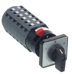
Понимание того, что происходит внутри корпуса переключателя, помогает избежать ошибок при выборе. 6-полюсный поворотный кулачковый переключатель состоит из шести модульных контактных блоков, смонтированных в осевом направлении. Каждая секция содержит клеммные винты, неподвижные контактные площадки, подпружиненный подвижный контактный мост и специально отлитое пластиковое кулачковое колесо. Когда оператор поворачивает внешнюю рукоятку из положения 0 в положение 1, центральный стальной приводной вал одновременно приводит в вращение все шесть кулачковых колес. Выступающие участки кулачка физически прижимаются к пружинным толкателям, удерживая контакты в размыкаемом состоянии, в то время как углублённые пазы позволяют внутренним пружинам замыкать контакты. Поскольку каждое кулачковое колесо может иметь уникальный профиль, один поворот на 60 или 90 градусов реализует заданную логику цепи по шести отдельным путям.
В системах переключения питания с двумя источниками для переключения небольшой промышленной распределительной панели с сетевого питания на резервный генератор, установленный на объекте, требуется размыкание трёх фаз под напряжением (L1, L2, L3) и нулевого провода (N), что составляет четыре основных полюса питания. Два дополнительных полюса на 6-полюсном переключателе (обычно настроенном на последовательность 1-0-2) обслуживают низковольтные цепи управления. Один полюс посылает сигнал запуска с «сухим» контактом на контроллер генератора, а второй дополнительный полюс переключает светодиодные индикаторы состояния на 24 В постоянного тока или отправляет входной сигнал обратно на ПЛК. Использование одного физического вала гарантирует, что переключение основного питания и сигналов управления происходит точно в одну и ту же миллисекунду.
Для управления многоскоростными двигателями при работе двухскоростных трехфазных асинхронных двигателей на шпинделях станков или вытяжных вентиляторах требуется изменить схему подключения обмоток двигателя к входящим линиям питания. 6-полюсный кулачковый переключатель обеспечивает переключение между низкоскоростной конфигурацией «треугольник» и высокоскоростной конфигурацией «двойная звезда». Переключатель физически перенаправляет входящие провода двигателя непосредственно на клеммах переключателя, устраняя необходимость в громоздких магнитных контакторах с блокировкой и дополнительной управляющей проводке.
Если требуется изменить направление вращения двигателя, достаточно поменять местами любые две фазные линии питания (L1 и L2), чтобы изменить направление вращения стандартного трехфазного двигателя переменного тока. В 6-полюсном переключателе два полюса используются для переключения фаз, третий полюс поддерживает подключение L3, а остальные три полюса служат для отключения вспомогательного питания катушек магнитных контакторов, блокировок защитных дверей или электромагнитных тормозов. Если оператор быстро переключает рукоятку из положения «Вперед» в положение «Назад», сначала размыкаются вспомогательные контакты, отключая главные силовые контакторы до того, как контакты, обеспечивающие изменение направления вращения, физически перекрестятся. Эта простая механическая задержка предотвращает разрушительные межфазные коротких замыкания на клеммных колодках.
Внутренние контактные площадки подвергаются высоким термическим нагрузкам во время операций переключения. Размыкание индуктивных двигательных нагрузок приводит к образованию сильной электрической дуги, которая может расплавить контакты низкого качества. Контакты из серебро-никелевого сплава (AgNi) идеально подходят для общих контуров управления и цепей резистивного нагрева с током до 32 А благодаря низкому контактному сопротивлению — менее 15 мОм. Контакты из оксида серебра и кадмия (AgCdO) необходимы для переключения мощных двигателей (категории AC-3 и AC-23A), поскольку AgCdO устойчив к эрозии дуги и сварке контактов при высоких пусковых токах. Всегда избегайте дешевых выключателей, в которых размыкание контактов зависит от скорости вращения рукоятки, и выбирайте модели с пружинными механизмами быстрого размыкания, которые размыкают или замыкают контакты менее чем за 8 миллисекунд.
Подключение к 12 или 24 отдельным винтовым клеммам на многоярусном кулачковом переключателе требует выполнения последовательных действий, чтобы предотвратить короткое замыкание. Всегда сверяйте схему цепи с таблицей состояний переключателя, чтобы убедиться, какие пары клемм замыкаются в каждом положении рукоятки. Многожильный медный провод может распушиться внутри узких клемм переключателя, поэтому всегда обжимайте изолированные наконечники типа «шнурок» на каждом конце провода, чтобы предотвратить соприкосновение свободных жил с соседними клеммами. Используйте динамометрическую отвертку для затяжки всех винтов клемм с усилием от 0,8 Нм до 1,2 Нм, так как чрезмерная затяжка приводит к растрескиванию хрупких корпусов переключателей, а недостаточная затяжка — к перегреву из-за высокого сопротивления.
При устранении неисправностей, связанных с однофазной работой двигателя, когда трехфазный двигатель громко гудит или срабатывает тепловой защитный выключатель, отключите питание от распределительного щита, отсоедините провода двигателя, переведите выключатель в положение «ON» и измерьте сопротивление между каждыми полюсами с помощью мультиметра. Любое показание выше 0,5 Ом указывает на изношенные или окисленные контакты, что требует замены выключателя. Если при повороте рукоятки ощущается люфт или «губчатость» и отсутствует четкий тактильный щелчок, вероятно, вибрация станка или принудительные повороты привели к срыву центрального квадратного вала внутри пластиковых кулачковых втулок. В этом случае следует заменить весь узел выключателя, а не пытаться отремонтировать внутренние пластиковые кулачки на месте.