



A protection relay order usually arrives with the single-line diagram attached and one question underneath it: which model covers this bay? The honest answer is that the model follows the application, and the application is decided by what the bay protects. Below is how we work through it with the ACX6300 range, plus the three order details that catch people out.
Scope note: this covers microprocessor protection relays for incoming, feeder, motor, transformer, capacitor, bus-coupler and PT circuits at 35 kV and below. Generator protection and transmission-line distance schemes are outside this range. ACXION builds these devices, so the guidance comes from the manufacturing side.
Three platforms, and why the split matters
The ACX6300 family is not one product with options. It is three separate hardware platforms, and each has its own enclosure, terminal arrangement and depth.
| Item | ACX6300K | ACX6300Q | ACX6300L |
|---|---|---|---|
| Current input | 5 A / 1 A | 5 A / 1 A | 5 A / 1 A |
| Zero-sequence current | 5 A / 1 A | 5 A / 1 A | 5 A / 1 A |
| Device supply | AC/DC 80 to 270 V | AC/DC 80 to 270 V | AC/DC 80 to 270 V |
| Separate operating supply | not required | AC/DC 110 or 220 V | AC/DC 110 or 220 V |
| Anti-pumping option | no | optional | optional |
| Communication | available | available | available |
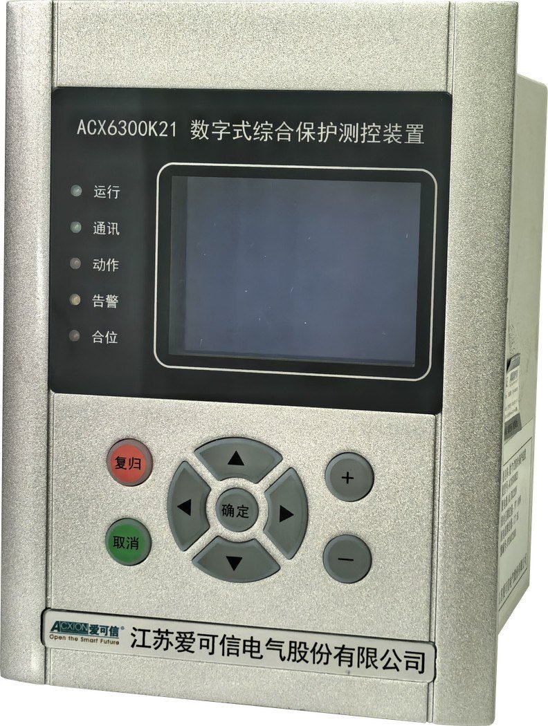
The K platform needs no separate operating supply. That single line decides a lot of small-substation projects, because a cubicle with only a device supply and no station battery can use K and nothing else.
Q and L take an operating supply of 110 or 220 V AC/DC and offer the anti-pumping option, which holds the breaker from re-closing while a trip command is still standing. On a feeder where the protection trips and the operator pushes close at the same moment, anti-pumping is what stops the breaker from pumping against the fault.
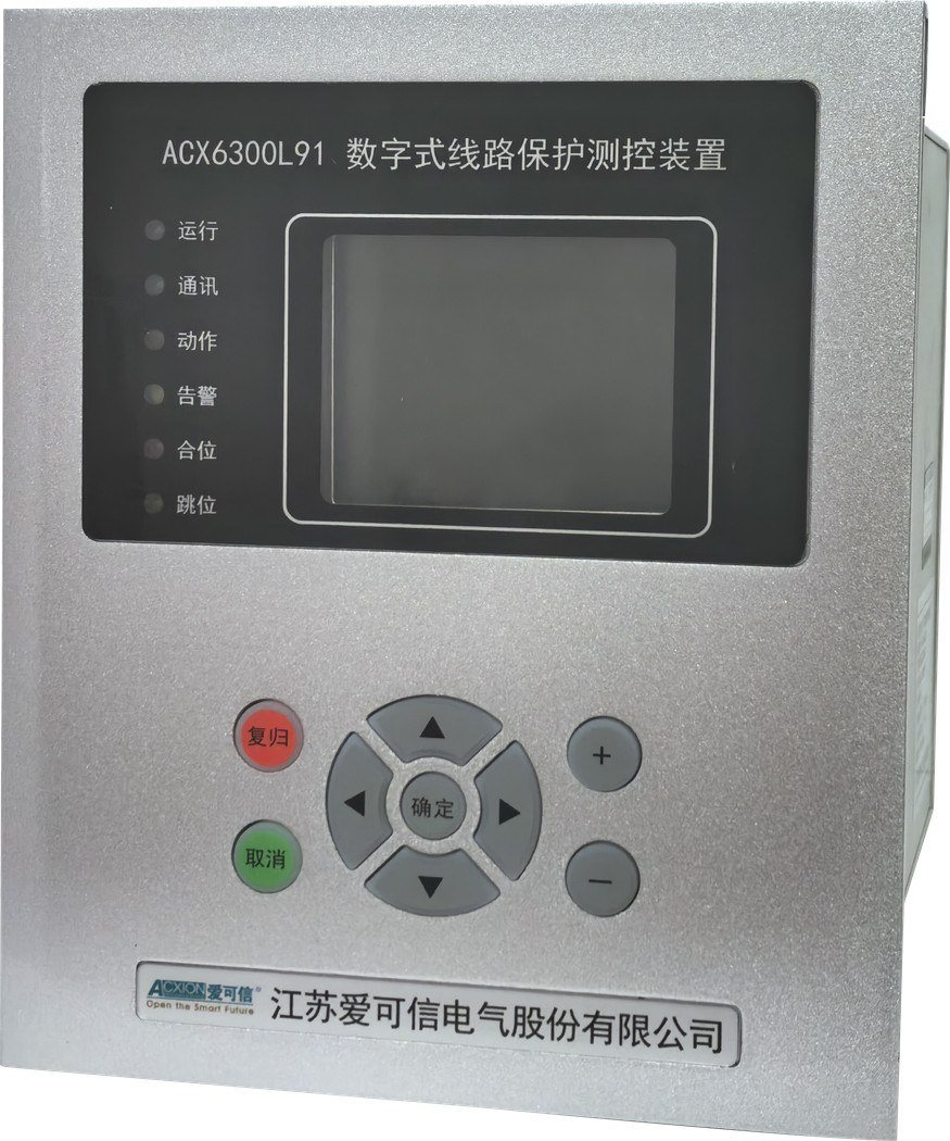
Model coverage runs like this. K21 for line and transformer protection, K25 for motors, K29 for PT monitoring. On the Q platform, Q31 line and transformer, Q34 capacitors, Q35 motors, Q38 automatic transfer, Q39 PT monitoring. The L platform is the widest: L91 line, L92 bus coupler, L93 transformer, L94 capacitor, L95 motor, L98 automatic transfer, L99 PT monitoring.
Match the function set to the bay
The function list is the real selection criterion. Protection functions are grouped by what the bay is, not by current rating.
| Application | Model options | Typical protection functions |
|---|---|---|
| Incoming or feeder | K21 / Q31 / L91 | Multi-stage overcurrent, negative sequence, earth fault, voltage, frequency, reclosing |
| Motor | K25 / Q35 / L95 | Short circuit, overload, negative sequence, start time, earth fault, thermal |
| Transformer | K21 / Q31 / L93 | Overcurrent, negative sequence, zero sequence, overload, voltage, non-electrical |
| Capacitor bank | Q34 / L94 | Overcurrent, earth fault, over and undervoltage, unbalance |
| Bus coupler | L92 | Charging, overcurrent, overload, control-circuit monitoring |
| Automatic transfer | Q38 / L98 | Source supervision and transfer logic |
| PT monitoring | K29 / Q39 / L99 | Over and undervoltage, loss of voltage, PT circuit supervision |
Two selection errors show up often enough to name.
The first is using a feeder model on a capacitor bank. Capacitor switching produces inrush and the bank runs with a deliberate current unbalance, so the dedicated unbalance and overvoltage functions matter. Q34 and L94 exist for that reason. A K21 in the same position will trip on things the bank does normally.
The second is over-specifying the platform. A 400 V auxiliary panel feeding four small feeders does not need an L-series device with transformer differential functions. The extra cost is not the problem; the extra settings that nobody commissions properly are.
The functions above are portfolio summaries. They are not a substitute for a project protection schedule, and the settings come from the study, not from the catalogue.
Device class is the other thing to keep straight. Relays of this type sit under IEC 60255 for measuring relays and protection equipment, with the GB/T 14598 series as the Chinese equivalent. Naming the standard matters at tender stage, because that is where a specification sometimes asks for a test report that the device class does not produce. Ask early rather than after the order.
Three order details that cause problems
Current input rating against the actual CTs
The relay reads 5 A or 1 A, and the order must state which. We had one order where the drawing showed 600/1 CTs and the specification line said nothing about the secondary, so the device was built with 5 A inputs. Commissioning found it: every reading was one fifth of the real value, and the trip thresholds inherited the same error. Nothing was damaged. Two panels in that substation had to be reconfigured and the devices exchanged.
Since then we ask for the CT ratio and the secondary current on the same line, plus the VT ratio for the voltage inputs. Both numbers go onto the order confirmation.
Panel depth behind the device
The three platforms do not share a depth. The K front is 172.0 x 128.2 mm with a cut-out of 155.5 x 125.0 mm and 86.5 mm overall depth. Q is 224.5 x 153.0 mm on the front, cut-out 209.0 x 150.0 mm, 79.2 mm deep. L has a 150.3 x 178.0 mm face and a much deeper body: 180.5 mm, or 195 mm including the terminal area.
That last figure catches panel builders. In a 600 mm deep cubicle with the CT terminal block mounted directly behind the relay, the wiring bends ended up tighter than the minimum the cable manufacturer allows, and the shielded control cable had to be re-routed. We now ask for the mounting plate depth and, where possible, a photo of the cubicle interior with the relay position marked.
Anti-pumping on the transfer schemes
On Q38 and L98 automatic transfer devices, anti-pumping interacts with the transfer logic. If the source supervision is set to transfer back after a short delay and the trip signal has not reset, the two functions can argue with each other during commissioning. This is a settings issue rather than a hardware one, but it is worth deciding the reset behaviour before the panel is wired, because changing it afterwards means rewiring part of the close circuit.
What the handover needs to include
Protection relays fail as projects more often than they fail as devices. The handover pack is where that gets fixed. Ours includes the protection setting file, the CT and VT ratios, the trip and close logic, the binary input and output list, the communication map for the Modbus loop, and the panel cut-out and wiring drawing.
Two of those deserve attention. The binary I/O list is what the SCADA integrator needs, and it is the document that gets requested most often after delivery. The wiring drawing for K, Q and L is not interchangeable, since the terminal arrangements differ between platforms. Commission only against the drawing supplied with the device.
Communication on all three platforms uses the standard protocol set for this class of device. Where the relay reports into a plant SCADA, that data path is normally the same Modbus-RTU loop used by the panel’s other monitoring devices.
Getting to a model
Send the single-line diagram, the CT and VT ratios, the bay type, the available supply in the cubicle and the panel depth. That is enough to name the platform, the model and the cut-out.
The K, Q and L model tables, protection matrices and dimension sets are in the power monitoring and protection catalogue on our download centre. Apparent relay problems are sometimes panel problems, and our existing notes on control panel troubleshooting cover the switch and indicator side of the same cabinet. Company background is on about ACXION, and setting files and handover questions go through the contact page. Further commissioning notes are collected on the ACXION blog.
Ratings in this article come from the current catalogue. Device supply, current input and cut-out dimensions are confirmed on the order confirmation, and the terminal drawing supplied with the device is the final authority.
Relays in this range are configured and quoted per project. Send the bay list and we will work up the configuration and the quotation.
By ACXION Engineering Team
One comment
Comments are closed.
[…] on our download centre. If the same installation also needs protection, our notes on choosing an ACX6300 protection relay by application cover that side of the […]