



A multifunction meter usually gets bought for the energy figure. Somebody wants kilowatt hours per shift, or per production line, and the meter goes in to deliver that number. The harmonic screen is the part nobody opens for the first year. Then a neutral terminal runs warm, or a capacitor bank starts losing fuses, and the same meter becomes the most useful instrument in the cabinet.
Scope note: this covers reading harmonics on a permanently installed panel meter, on low voltage and medium voltage distribution, up to the thirty-first harmonic. It is not a substitute for a compliance survey with a portable power quality analyser, and it does not cover interharmonics, flicker or dip statistics. ACXION builds the TS series meters discussed here, so this comes from the manufacturing and application side rather than from a test laboratory.
Why the neutral can carry more current than the phase
On a balanced three phase system feeding linear loads the neutral carries almost nothing. That is why neutral conductors are often sized smaller than the phase conductors. Switched mode power supplies change that. The current drawn by a rectifier front end is not sinusoidal. The third harmonic it produces does not cancel in the neutral the way the fundamental does. Third, ninth and fifteenth harmonics add in the neutral instead of cancelling.
We have measured neutral current above phase current on boards feeding nothing but LED lighting and desktop equipment. The phase readings looked comfortable, well inside the breaker rating, and the neutral was the one that ran warm. On four panels we looked at last year, the neutral was warmer than any phase. In every case the board had been designed on the assumption that the load was linear. Nothing on the nameplates would have revealed it.
A meter that only reports total current hides this completely. You need the harmonic content on the neutral, or at least the third harmonic on the phases, before deciding whether the neutral conductor is correctly sized.
Read the spectrum, not a single percentage
Most meters display total harmonic distortion as one number, and that number is where most people stop. It is the least useful figure on the screen. Eight per cent caused by a third harmonic is a different problem from eight per cent caused by an eleventh, and the remedy is not the same.
The order tells you the source. A dominant fifth and seventh points at a six pulse rectifier, which on plant usually means variable speed drives and the larger UPS units. A dominant third points at single phase electronic loads, and that is the neutral problem described above. Eleventh and thirteenth usually means a twelve pulse arrangement or a large DC drive. IEC 61000-4-7 sets out how harmonic and interharmonic measurements on a supply system should be grouped and evaluated. It is the reference we use when somebody asks why a fixed meter and a portable instrument disagree by a few tenths.
The TS multifunction meters report from the second to the thirty-first harmonic. That range covers what you are likely to meet on an industrial or commercial board. Anything above it belongs to a different class of instrument and a different kind of investigation.
Where the harmonics come from
The sources are almost always the same four, and once you know them you can usually predict the spectrum before you measure it. Variable frequency drives are the largest single contributor on most plant. Switched mode supplies in control cabinets, PLC racks and IT equipment contribute a broad third harmonic background that never switches off. Uninterruptible power supplies contribute according to their rectifier design. LED lighting contributes more than people expect on a large installation, because the number of fittings is high even where each one is small.
None of this is a fault in the equipment. Modern loads draw current in pulses and the supply has to cope with it. The question is only whether the distribution was designed for it, and usually it was not.
The capacitor bank trap
Power factor correction capacitors are what turn a manageable harmonic level into a failure. A capacitor is a low impedance at harmonic frequencies, so the bank absorbs harmonic current from the whole installation. If the bank inductance happens to resonate near a harmonic that is present, the current in that branch can climb far above what the fuses and contactors were selected for. Blown capacitor fuses, bulged cans and welded contactor contacts are the usual symptoms. They are routinely diagnosed as a capacitor quality problem.
We have been called to two panels where the capacitor bank was the visible failure. The real cause was a drive retrofit eighteen months earlier. The bank had been sized when the load was mostly motors, and harmonic current from the new drives found the resonant point straight away. In both cases the meter data settled the argument. The fifth harmonic current in the capacitor branch was several times the fundamental.
A detuned reactor in series with each stage is the standard answer. The reactor has to be selected against the harmonic order that is actually present, not against a generic value taken from a previous job.
Getting numbers you can trust
A harmonic reading is only as good as the current transformer feeding it. The TS meters take a CT secondary of 1 A or 5 A. Voltage input is 57.7/100 V or 220/380 V, direct or through a PT. They present a burden below 0.2 VA on both the current and voltage inputs. That last figure matters more than it looks. If the CT is small and the secondary wiring run is long, the burden in the cable can push the core into saturation. A saturated core reports harmonics that are not there.
Current and voltage are measured to Class 0.2, active power and active energy to Class 0.5, and reactive energy to Class 1. For harmonic work the voltage and current accuracy is the figure to check, because the harmonic content comes from the same front end. Frequency range is 45 to 65 Hz, and the continuous overload on the current input is 1.2 times rated.
On communications the meters run Modbus-RTU over RS485 at 2400, 4800, 9600 or 19200 bps, with 9600 as the default. In practice the limiting factor is rarely the baud rate. It is the polling rate of the SCADA master. A spectrum read once an hour will not show the peak that appears when a particular drive starts.
Panel format and option choices
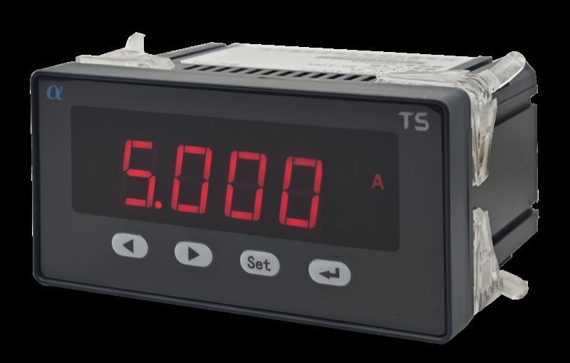
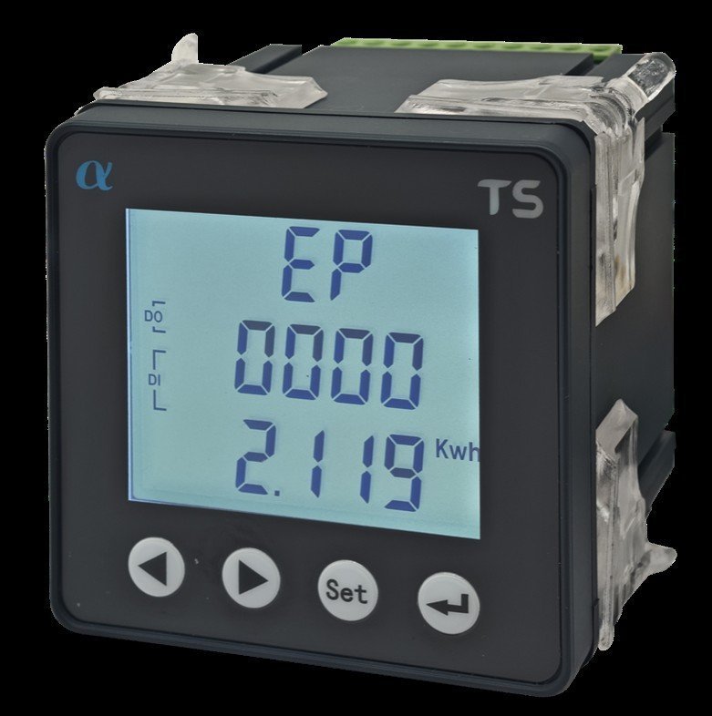
The meter has to fit the space that is left, and on a retrofit that space is whatever the previous instrument occupied. The TS series comes in 48, 72, 80 and 96 mm square formats, plus a 96 by 48 mm version. Cut-outs are 45 by 45, 68 by 68, 76 by 76 and 91 by 91 mm, and 91 by 45 mm on the wide version. A 96 mm unit has the screen area to show a spectrum legibly. That matters if an operator is expected to read it locally instead of over the bus.
Optional expansion covers one or two relay outputs, two or four digital inputs, and one to three analogue outputs at 4 to 20 mA or 0 to 20 mA. Which of these you need depends on whether the meter is only reporting or also acting, and not every combination fits every frame size. On the 96 by 48 mm DC meters the RS485 option and the single analogue output are mutually exclusive. That choice has to be made before ordering.
Supply is AC or DC 80 to 270 V at no more than 5 VA. Operating range is minus 10 to plus 55 degrees Celsius and the altitude limit is 2500 metres. Insulation between supply, inputs and outputs is above AC 2 kV.
The same platform covers DC measurement as well. Direct DC voltage input goes up to 1000 V, and current comes from a 75 mV shunt or a Hall sensor, at Class 0.5. That is the version solar and telecom boards need. It is a separate model family rather than an option on the AC meters.
What we ask before quoting a meter
We are the manufacturer, so it is only fair to say that we sell these and the guidance reflects that. What we need from you is not a purchase order. It is the system voltage, the CT ratio and secondary rating already installed, and whether voltage is direct or through a PT. Then the accuracy class you actually require, which expansion outputs you need, and how the readings will be collected.
Meters in this range are built to order from the catalogue and quoted per configuration. Model matrices, expansion codes, wiring arrangements and cut-out dimensions are in the TS series catalogue on our download centre. If the same installation also needs protection, our notes on choosing an ACX6300 protection relay by application cover that side of the panel.
What this article does not cover
Interharmonics, voltage flicker, dip and swell statistics, and compliance reporting against a utility tariff all sit outside what a panel meter is meant to do. If the question is whether an installation meets the harmonic limits the network operator sets, that needs a portable analyser over a survey period. IEEE 519 is the usual reference for what those limits should be. A permanently installed meter tells you what is happening on a Tuesday afternoon. It does not, on its own, tell you what the utility will say about it.
Ratings here come from the current catalogue. Confirm the model code and expansion combination on the order confirmation, and treat the wiring diagram supplied with the device as the final authority.